Serial enabled 14 segment alphanumeric LED
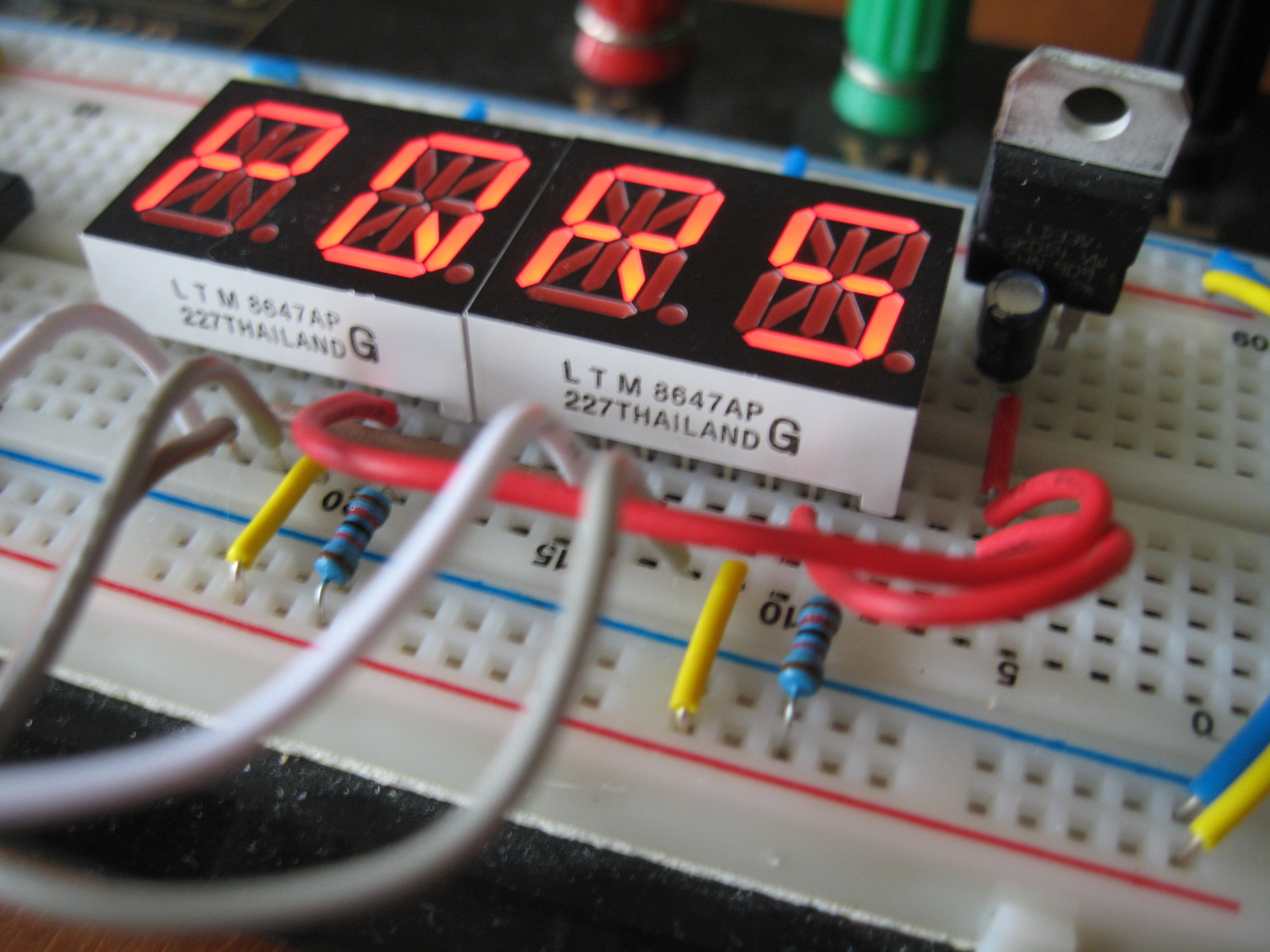
I purchased two Liteon LTP-8647AP Dual 14-Segment alphanumeric LED from Jameco (about $3 each). These displays are unique in that they have a M5450 chip inside them that allows serial communication, minimizing wires and related chips. The only down side to them is the M5450 does not have a built in character set, and I had to build one by hand.
All inputs are TTL level compatible, but it still needs a 3.3 volt supply for the LEDs. This is some really cool tech, unfortunately, it is tech from the 1980's and these chips are hard to find. I used 12k resistors to control the brightness of the LED's. You might want to go with 10k to brighten them up a little more.
This was one of my first experiments with multiplexing multiple chips. If I am calculating correctly, I could control 90 chips off of one ATMega168 processor. One clock, ten data enable pins, and 9 data pins.
The brown wire on pin 5 is the clock.
The gray wire on pin 6 are the chip select pins.
The white wire on pin 4 are the data pins.
Yellow wires are +5vdc
Red wires are +3.3vdc
Blue is ground
Purchase from jameco.com
Datasheet

As am added bonus, I included code to flip the character set upside down. Then you just need to re-order the data and data enable pins and swap the c1 and c2 in print_led. Up-side down fonts for up-side down chips, a clever solution for a problem that does not exist. Your welcome.
// LITE-ON, LTP-8647AP, 2 digit, 14-Segment Red LED
// Jameco.com, part no. 1955933, $2.95
// http://www.jameco.com/webapp/wcs/stores/servlet/Product_10001_10001_1955933_-1
//
// Code by Scott Cooper

// The code is setup to multiplex the data_pins and the data_enable_pins.
// This allows for a single ATMEGA168 to run up to 100 chips or 200 characters at a time (10x10)
// In this example the first chips is connected to pins 3 and 5.
// The second chip is connected to pins 4 and 6.
// All chips will use the same clock.

// The only pins needed to run the LTP-8647 chip:

//       4  data enable
//       5  clock
//       6  data
//       7  +5vdc
//       8  +3.3vdc
//       9  12k resistor going to Gnd, brightness
//      14  Gnd

const int total_chars  = 4;
int clock_pin          = 2;      // set clock pin
int data_enable_pins[] = {3, 4}; // set slave select pins
int data_pins[]        = {5, 6}; // set master out, slave in pins
int font[64];
int c;
char buf[16]           = \"\";

///////////////////////////////////////////////////////////////////////////////////////////////////////
void setup() {

  // Add 32 to the font index to get the corresponding ASCII value
  font[0]  = 0;     // space
  font[1]  = 6144;  // !
  font[2]  = 272;   // \"
  font[3]  = 16383; // #
  font[4]  = 11730; // $
  font[5]  = 2541;  // %
  font[6]  = 11309; // &
  font[7]  = 8;     // \'
  font[8]  = 12;    // (
  font[9]  = 33;    // )
  font[10] = 255;   // *
  font[11] = 210;   // +
  font[12] = 1;     // ,
  font[13] = 192;   // -
  font[14] = 1666;  // .
  font[15] = 9;     // /
  font[16] = 16137; // 0
  font[17] = 6144;  // 1
  font[18] = 14016; // 2
  font[19] = 15424; // 3
  font[20] = 6592;  // 4
  font[21] = 9604;  // 5
  font[22] = 12224; // 6
  font[23] = 14336; // 7
  font[24] = 16320; // 8
  font[25] = 15808; // 9
  font[26] = 18;    // :
  font[27] = 17;    // ;
  font[28] = 12;    // <
  font[29] = 1216;  // =
  font[30] = 33;    // >
  font[31] = 12354; //
  font[32] = 14160; // @
  font[33] = 15296; // A
  font[34] = 15442; // B
  font[35] = 9984;  // C
  font[36] = 15378; // D
  font[37] = 10176; // E
  font[38] = 9088;  // F
  font[39] = 12096; // G
  font[40] = 7104;  // H
  font[41] = 18;    // I
  font[42] = 7680;  // J
  font[43] = 908;   // K
  font[44] = 1792;  // L
  font[45] = 6952;  // M
  font[46] = 6948;  // N
  font[47] = 16128; // O
  font[48] = 13248; // P
  font[49] = 16132; // Q
  font[50] = 13252; // R
  font[51] = 11712; // S
  font[52] = 8210;  // T
  font[53] = 7936;  // U
  font[54] = 777;   // V
  font[55] = 6917;  // W
  font[56] = 45;    // X
  font[57] = 42;    // Y
  font[58] = 9225;  // Z
  font[59] = 9984;  // [
  font[60] = 36;    // backslash
  font[61] = 15360; // ]
  font[62] = 12297; // ^
  font[63] = 1024;  // _
  //flip_font_upside_down();

  Serial.begin(9600);                        // open the serial port at 9600 bps:
  pinMode(clock_pin, OUTPUT);                // set SCK pin to output

  for (int i=0; i     pinMode(data_enable_pins[i], OUTPUT);    // set CS pin to output
    digitalWrite(data_enable_pins[i], HIGH); // hold slave select 1 pin high, so that chip is not selected to begin with
  }

  for (int i=0; i     pinMode(data_pins[i], OUTPUT);           // set MOSI pin to output
  }

  print_led(\"    \");
}

///////////////////////////////////////////////////////////////////////////////////////////////////////
void loop () {
  // Output entire font.
  for (int i=32; i<95; i+=4) {
    sprintf(buf, \"%c%c%c%c\", char(i), char(i+1), char(i+2), char(i+3));
    print_led(buf);
    delay(500);
  }

  print_led(\"TEST WITH TOO MANY CHARS\");
  delay(1000);

  print_led(\"caSe\");
  delay(1000);

  // Quickly dump some numbers
  for (int i=2000; i>0; i--) {
    sprintf(buf, \"%d   \", i);
    print_led(buf);
  }
}

///////////////////////////////////////////////////////////////////////////////////////////////////////
void print_led (char mystr[]) {
  for (int i=0; i     spi_out(data_pins[(i+1)/2], data_enable_pins[(i+1)/2], mystr[i],  mystr[i+1]);
  }
}

///////////////////////////////////////////////////////////////////////////////////////////////////////
void spi_out(int data_pin, int data_enable_pin, char c1, char c2) {
  unsigned long working;

  if (c1 >= 97 && c1 <= 122) { c1-=32; }  // check for lower case
  if (c2 >= 97 && c2 <= 122) { c2-=32; }  // check for lower case
  if (c1 < 32) { c1=\' \'; }                // check for too small
  if (c2 < 32) { c2=\' \'; }                // check for too small
  if (c1 > 95) { c1=\' \'; }                // check for too big
  if (c2 > 95) { c2=\' \'; }                // check for too big

  c1-=32;
  c2-=32;

  working = 1;
  working = working << 14;
  working += font[c2];
  working = working << 14;
  working += font[c1];
  working = working << 3;
  // Bits 32, 33 & 34 are not accessible because the long is only 32 bits.

  digitalWrite(data_enable_pin, LOW); // set low to enable this led.

  for(int i = 0; i <= 35; i++) {
    digitalWrite(clock_pin, LOW);

    //if(i == 2) { Serial.print(\" \"); }
    //if(i == 16) { Serial.print(\" \"); }
    //if(i == 30) { Serial.print(\" \"); }
    //if(i == 33) { Serial.print(\" \"); }

    if (working > 2147483647) { // test the most significant bit
      //Serial.print(\"1\");
      digitalWrite (data_pin, HIGH); // if it is a 1 (ie. B1XXXXXXX), set the master out pin high
    } else {
      //Serial.print(\"0\");
      digitalWrite (data_pin, LOW); // if it is not 1 (ie. B0XXXXXXX), set the master out pin low
    }
    digitalWrite (clock_pin,HIGH); // set clock high, the pot IC will read the bit into its register
    working = working << 1;
  }

  //Serial.print(\"  \");
  //Serial.print(c2, BYTE);
  //Serial.print(\"  \");
  //Serial.print(c1, BYTE);
  //Serial.println();
  digitalWrite(data_enable_pin, HIGH); // set high to disable this led.
}

///////////////////////////////////////////////////////////////////////////////////////////////////////
// Some sweet little un-necessary bit fiddling and the whole font can be flipped upside down
// Just reorder the data_pins and the data_enable pins, and swap c1 & c2 in print_led
void flip_font_upside_down() {
  int newfont;

  for(int i=0; i<=63; i++) {

    newfont = 0;
    if(font[i] & 8192) { newfont+=1024; };
    if(font[i] & 4096) { newfont+=512;  };
    if(font[i] & 2048) { newfont+=256;  };
    if(font[i] & 1024) { newfont+=8192; };
    if(font[i] & 512)  { newfont+=4096; };
    if(font[i] & 256)  { newfont+=2048; };
    if(font[i] & 128)  { newfont+=64;   };
    if(font[i] & 64)   { newfont+=128;  };
    if(font[i] & 32)   { newfont+=4;    };
    if(font[i] & 16)   { newfont+=2;    };
    if(font[i] & 8)    { newfont+=1;    };
    if(font[i] & 4)    { newfont+=32;   };
    if(font[i] & 2)    { newfont+=16;   };
    if(font[i] & 1)    { newfont+=8;    };

    font[i] = newfont;
  }
}

///////////////////////////////////////////////////////////////////////////////////////////////////////
created: Dec. 1, 2013, 1:01 a.m.
modified: April 13, 2019, 5:09 p.m.